Siemens - Passerelles KNX / DALI - RailDIN
N 141/03
- With emergency lighting, with sensors
- For communication via KNX with electronic ballasts (ECG) with a DALI interface
- DALI outputs with DALI-2 certification acc. to IEC 62386-101 and 103, each for communication with up to 64 DALI ECG Ed.1 and DALI-2 and at least 10 sensors
- Integrated power supply with input voltage AC 110-240 V, 50-60 Hz or DC 120-240 V for powering the gateway electronics and DALI output
- Maximum DALI output voltage of 19 V, short circuit resistant
- Incorrect voltage detection during commissioning if incorrect power line is connected to a DALI output
- LED display for displaying operation mode and error messages
- Pushbutton for switching between bus and direct operating mode
- One pair of pushbuttons for switching On/Off of all connected DALI ECG
- One LED per DALI output for status signal of all connected luminaries in direct mode
- Configurable assignment of max. 64 DALI ECG per channel to max. 16 DALI groups per channel, exclusive controlled in groups or single (switching, dimming, set dimming value and color temperature) and feedback for group status and lamp failure
- Support of DALI DT8 ECGs for colour temperature control (Tunable White). Individual, group, scene, effect and schedule control for Human Centric Lighting
- Configurable behaviour for bus failure (stand-alone mode)
- Configurable pre-loaded applications without software ETS
- Configurable function burn-in for all ECG via pushbutton or single via object
- Scheduler for day, week, date with astro function
- Control of all connected luminaries together in broadcast mode
- Status signal and display of lamp and ECG failure per group and per DALI device
- Transformation of dimming commands into a temporary setpoint adjustment for ECG with integrated constant light level control and directly connected light level sensor
- One or two level timer
- Up to 4 integrated one time or cyclical control of repeatable sequences or color effects
- Distinction between self-contained emergency luminaries with one or two DALI devices
- Starting the self-conducted testing of each individual inverter and reporting the test result via bus or save in a persistent memory with memory space monitoring over object
- Distinction between function test, short duration test, and long duration test
- Optional configuration of any DALI ECG to dim to a preset dimming value in case of emergency mode
- Locking of switching and dimming commands as well as configuration while emergency mode is activated
- Activation of emergency mode based on a configurable number of failed DALI ECG
- Lock object to elimination of failure messages interruption of ECG during emergency lighting testing
- Inhibit mode for disabling battery mode of self-contained emergency luminaries over pushbutton
- Per channel up to 6 stand-by-area analysis for activation of switch actuators
- Scene control for up to 16 scenes per channel
- 16 integrated 2-level-controller for brightness control and 16 constant light level controller for main luminaries group and up to 4 additional luminaries groups
- Assignment of a CIN to a DALI ECG
- Reintegration defective DALI ECG without ETS
- Assignment of DALI ECG to groups and test option for ECG, groups, scenes and effects via ETS
- Assignment of DALI sensors and test option of sensors via ETS
- Integrated bus coupling unit with only half a standard bus load, bus connection via bus terminal
- Mounting on DIN rail EN 60715-TH35-7.5
N 141/21
- With emergency lighting, with sensors
- For communication via KNX EIB with electronic ballasts (ECG) with a DALI interface
- Two DALI outputs with DALI-2 certification acc. to IEC 62386-101 and 103, each for communication with up to 64 DALI ECG Ed.1 and DALI-2 and at least 10 sensors
- Integrated power supply with input voltage AC 110-240 V, 50-60 Hz or DC 120-240 V for powering the gateway electronics and DALI output
- Maximum DALI output voltage of 19 V, short circuit resistant
- Incorrect voltage detection during commissioning if incorrect power line is connected to a DALI output
- LED display for displaying operation mode and error messages
- Pushbutton for switching between bus and direct operating mode
- One pair of pushbuttons for switching On/Off of all connected DALI ECG
- One LED per DALI output for status signal of all connected luminaries in direct mode
- Configurable assignment of max. 64 DALI ECG per channel to max. 16 DALI groups per channel, exclusive controlled in groups or single (switching, dimming, set dimming value and color temperature) and feedback for group status and lamp failure
- Support of DALI DT8 ECGs for colour temperature control (Tunable White). Individual, group, scene, effect and schedule control for Human Centric Lighting
- Configurable behaviour for bus failure (stand-alone mode)
- Configurable pre-loaded applications without software ETS
- Configurable function burn-in for all ECG via pushbutton or single via object
- Scheduler for day, week, date with astro function
- Control of all connected luminaries together in broadcast mode
- Status signal and display of lamp and ECG failure per group and per DALI device
- Transformation of dimming commands into a temporary setpoint adjustment for ECG with integrated constant light level control and directly connected light level sensor
- One or two level timer
- Up to 4 integrated one time or cyclical control of repeatable sequences or color effects
- Distinction between self-contained emergency luminaries with one or two DALI devices
- Starting the self-conducted testing of each individual inverter and reporting the test result via bus or save in a persistent memory with memory space monitoring over object
- Distinction between function test, short duration test, and long duration test
- Optional configuration of any DALI ECG to dim to a preset dimming value in of emergency mode
- Locking of switching and dimming commands as well as configuration while emergency mode is activated
- Activation of emergency mode based on a configurable number of failed DALI ECG
- Lock object to elimination of failure messages interruption of ECG during emergency lighting testing
- Inhibit mode for disabling battery mode of self-contained emergency luminaries over pushbutton
- Per channel up to 6 stand-by-area analysis for activation of switch actuators
- Scene control for up to 16 scenes per channel
- 16 integrated 2-level-controller for brightness control and 16 constant light level controller for main luminaries group and up to 4 additional luminaries groups
- Assignment of a CIN to a DALI ECG
- Reintegration defective DALI ECG without ETS
- Assignment of DALI ECG to groups and test option for ECG, groups, scenes and effects via ETS
- Assignment of DALI sensors and test option of sensors via ETS
- Integrated bus coupling unit with only half a standard bus load, bus connection via bus terminal
- Mounting on DIN rail EN 60715-TH35-7.5
N 141/31
- Communication via KNX EIB avec ballasts électroniques (ECG) avec une interface DALI
- Deux (2) sorties DALI selon la norme IEC 62386, chacune pour la communication avec jusqu'à 64 ballasts DALI et au moins 10 capteurs
- Alimentation intégrée avec tension d'entrée de 110...240 V CA, 50...60 Hz ou 120...240 V CC pour l'alimentation de l'électronique de passerelle et de la sortie DALI
- Tension de sortie DALI maximale de 19 V, résistante aux courts-circuits
- Détection de tension incorrecte lors de la mise en service, en cas de connexion d'une ligne électrique inappropriée à une sortie DALI
- Affichage LC pour afficher le mode de fonctionnement et les messages d'erreur
- Bouton-poussoir de commutation entre le mode bus et le mode de fonctionnement direct
- Une paire de touches pour activer/couper tous les ballasts DALI connectés
- Une LED par sortie DALI pour le signal de l'état de tous les luminaires connectés en mode direct
- Affectation configurable de 128 ballasts DALI maximum à jusqu'à 32 groupes DALI maximum, contrôlés exclusivement par groupes (commutation, variation, valeur de variation réglée) et retour pour l'état du groupe et la défaillance de la lampe
- Comportement configurable pour la défaillance du bus (mode autonome)
- Commande (commutation, variation, valeur de variation réglée) de tous les luminaires connectés ensemble en mode diffusion
- Signal d'état et affichage de la défaillance du luminaire et du ballast par groupe et par appareil DALI
- Il est possible de réintégrer le ballast DALI défectueux sans logiciel
- Minuterie à un ou deux niveaux
- Commande intégrée de scénarios pour jusqu'à 32 scénarios
- 16 contrôleurs intégrés à 2 niveaux pour la régulation de la luminosité
- Affectation du ballast DALI aux groupes et option de test pour le ballast, les groupes et les scénarios via ETS lors de la mise en service
- Affectation des capteurs DALI et option de test des capteurs via ETS pendant la mise en service
- Coupleur de bus intégré avec demi-charge de bus standard seulement, par raccordement du bus par borne
- Montage sur rail selon la norme DIN EN 60715-TH35-7.5
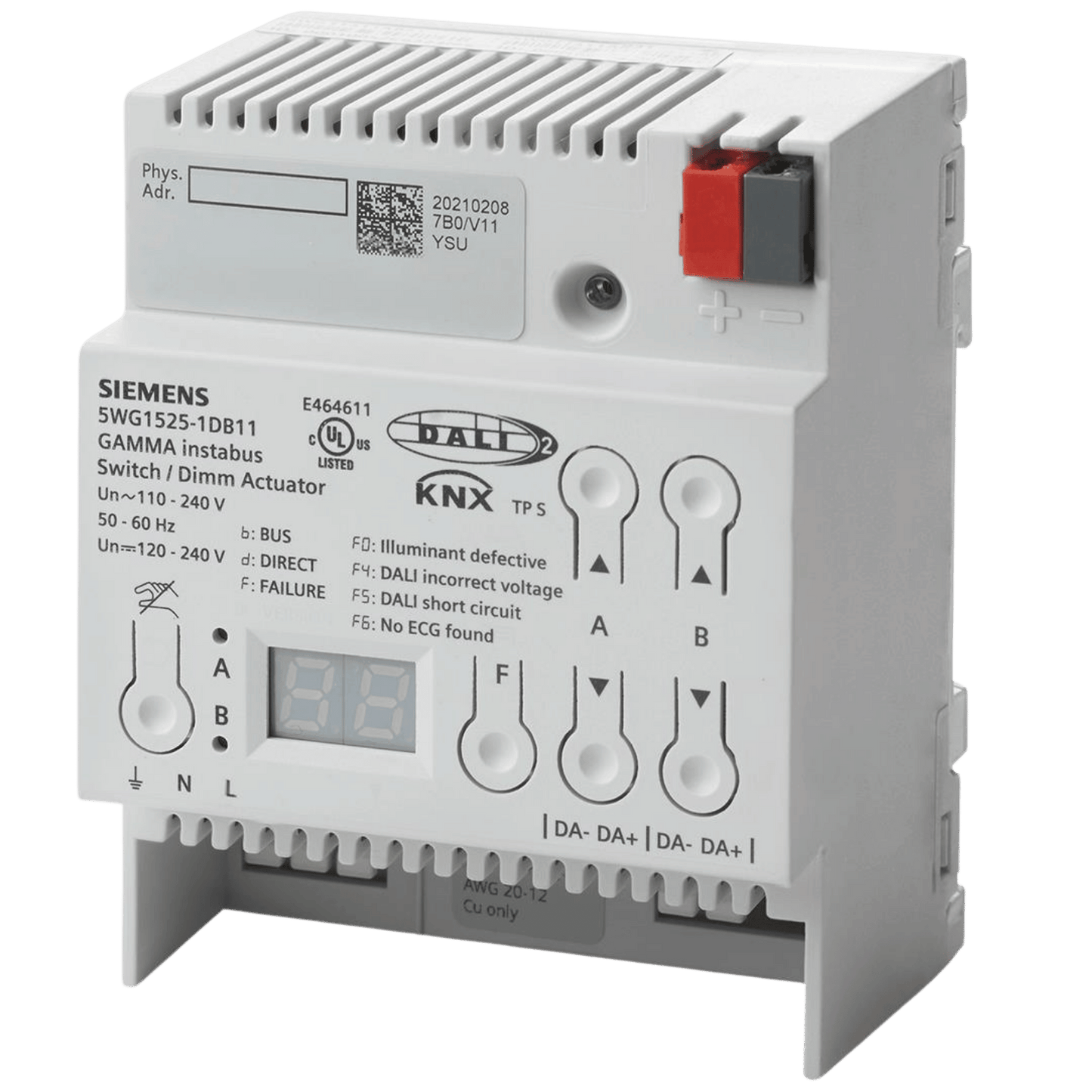
N 525D11
• 2 DALI outputs with DALI-2 certification
• Control capacity for up to 20 DALI-ECGs per DALI output
• DALI output voltage of 19 V, short circuit resistant
• Integrated power supply with input voltage AC 110-240 V, 50-60 Hz or DC 120-240 V for powering the gateway electronics and DALI output
• LED display for displaying operation mode and the following failure messages: Illuminant defective, DALI incorrect voltage, DALI short circuit, no ECG found
• One pair of push buttons for switching On/Off and dimming of all connected DALI ECG
• Button on the device front for deactivation of the direct mode operation and LED to indicate activation direct mode operation
• Building site function that provides ex-factory enables switching the building site lighting on and off via bus wall switches and actuators, even if these devices have not yet been commissioned with the Engineering Tool Software (ETS)
• Housing: plastic, N-system
• DIN rail mounted device for mounting on rail TH35 according to DIN EN 60715
• Type of protection: IP 20
• Max. width 4 TE (1 TE = 18 mm)
Partager